Introduction
I am currently building a rocket engine. This post covers the design of the engine, including its combustion chamber, ignition system and the window used to observe its insides. I’m doing this for several reasons. First, I love engineering and rockets. I have always wanted to build a rocket engine and now I have the impetus to do so. Second, I want to capture video footage of the inside of the rocket engine. This is something that has either never been done or never been publicly broadcasted across the internet. As a result, I will demonstrate that it is possible to experimentally confirm the results of CFD simulations describing the interior of a rocket engine. Third, this project will require me to review and expand my skillset, allowing me to grow and become a better engineer. And finally, I am extremely passionate and want to share this with other engineers and potential employers so that I may use my abilities to contribute to something greater.
Brief Design Overview
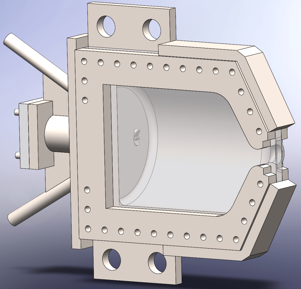
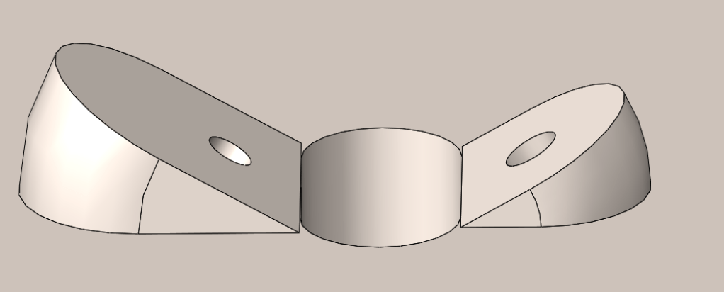
The Pliny rocket engine is a pressure fed rocket engine designed with a window to allow ignition and combustion to be filmed. Pliny is designed to achieve a chamber pressure of 0.5 Megapascals using liquid oxygen and gasoline as its propellants. The designed mass flow rate is 6.1555 grams per second, with 4.0485 grams per second of liquid oxygen and 2.107 grams per second of gasoline. The combustion chamber is made from 316L stainless steel because it retains its strength and ductility at low temperatures.[1] The fuel and oxidizer converge at an unlike doublet injector centered on the igniter. The window is made from sapphire because of its excellent tensile strength and high heat resistance for a transparent material. The window is bolted to the combustion chamber. There is a piece which distributes the compressive load from the bolts across the window. The igniter is custom, made primarily of a refractory ceramic with a high dielectric strength, ideally Boron Nitride. The final decision will be determined off of cost and dielectric strength. Inside this ceramic casing are two tubes with wires running through them. The wires enter the engine to create an electric arc inside the combustion chamber, igniting the propellants. I will rent a slow motion camera to film the rocket engine throughout its test fire. This camera will most likely be a Freefly wave camera because it can film at up to 9259 frames per second, enough to capture ignition at reasonable resolution.
Detailed Design of the Pliny Rocket Engine
This section expands upon the information I shared in the brief design overview, giving insights into the design choices I made by providing technical reasoning.
Propellant Mixture
The Pliny rocket engine uses liquid oxygen and gasoline as its two propellants. I chose liquid oxygen as the oxidizer because it is readily available, releases large amounts of energy when it reacts with most fuels and is used by most launch companies. I selected gasoline as the fuel because it is inexpensive, easy to obtain and energy dense.
I used a program known as CEARUN, an online version of the NASA chemical equilibrium code CEA (Chemical Equilibrium with Applications) to calculate the optimal proportion of fuel in the engine. CEA allows the user to explicitly define the composition and properties of the fuel and oxidizer, determine the ratio of fuel to oxidizer, set the chamber pressure and use multiple different methods of solving the rocket problem.[2]
Since gasoline has a highly variable composition made from hundreds of hydrocarbons, I needed to define an arbitrary mixture which was reasonably similar to the gasoline components. I found a mixture from a scientific paper, Octane Number Determination of Gasoline With a Phononic Crystal Sensor, to be adequate.[3] I used a preset of liquid oxygen as the oxidizer in CEA.
| Compound | Percent Volume | Percent Weight |
| n-heptane (C7H16) | 3.9% | 3.608% |
| n-hexane (C6H14) | 17.1% | 15.381% |
| iso-octane (C8H18) | 42.1% | 39.665% |
| cyclopentane (C5H10) | 6.6% | 6.701% |
| ethanol (C2H5OH) | 10% | 10.747% |
| ethylbenzene (C8H10) | 20.3% | 23.9645% |
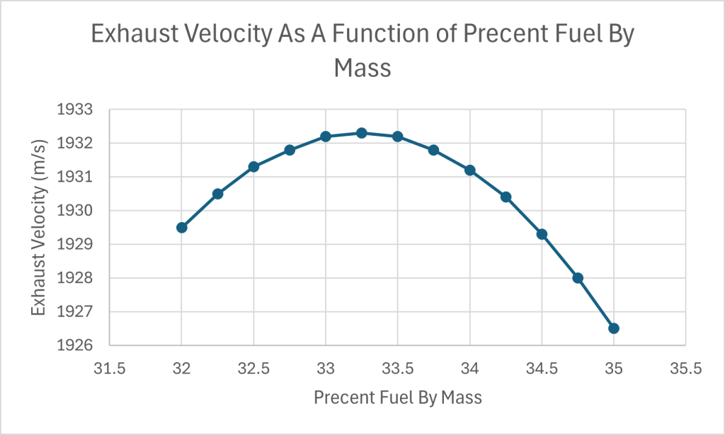
I found that the exhaust velocity, measured in meters per second, peaks when the Pliny uses 33.25% fuel by weight. This combustion is fuel rich and results in an exhaust composed of 50.3% by weight carbon monoxide, 21.1% carbon dioxide, 25.8% water and 1.6% percent by mass hydrogen. The leftover components combined amount to approximately a percent of the exhaust. The reason why the exhaust velocity peaks at 33.25% fuel is because carbon monoxide is less massive than carbon dioxide. Since lighter molecules move faster for a given temperature, it can compensate for how the falling combustion temperature reduces the amount of heat energy available.
Combustion Chamber
The combustion chamber is made of 316L stainless steel. I choose this material because it is readily available at most metal 3D printing services. Furthermore, it is still ductile at cryogenic temperatures, meaning that it can accommodate the flow of liquid oxygen through it without risking failure.[4] The combustion chamber is exceedingly large relative to the nozzle in order to increase the propellant stay time to 19.2 milliseconds. This is significantly longer than the propellant stay time of most rocket engines, with stay times of 1 millisecond[5] and 6.27 milliseconds[6] more typical. As a result, the Pliny is likely to have complete combustion occur inside its combustion chamber.
The combustion chamber’s wall is 1.65 mm thick with the primary constraint being thermal in nature. Via hand calculations using the formula for hoop stress a safety factor slightly greater than 2 and a value of 205 MPa as the yield strength of 316L stainless steel[7], I determined that the minimum thickness the combustion chamber with a factor of safety of 2 is approximately 0.14mm. As a result, a combustion chamber which can be 3D printed will not suffer a structural failure. However, I also need to prevent engine rich combustion. I plan to use a simple water based cooling system to hold the exterior temperature of the combustion chamber to 100 degrees Celsius (212 degrees Fahrenheit). This can be modeled as conduction through a wall. I found the thermal conductivity of 316L stainless steel to be 15 W/m*K[8], assumed off of various papers[9][10] which use engines with chamber pressures similar to the Pliny that I should design around a heat flux of 10 MW/m2. I also required that the internal surface of the engine must remain at 1200 Co. With this information, I calculated the maximum allowable thickness of the combustion chamber using a variation of Fourier’s law of heat conduction, a value of 1.65mm.[11] This became the thickness of my combustion chamber since it was thick enough to be structurally sound yet thin enough that I would likely be able to prevent engine rich combustion.
The Pliny is currently designed to be mounted to the test stand via four 1 centimeter diameter bolts. This part of the design is likely to be revised in the future as I design the engine’s test stand.
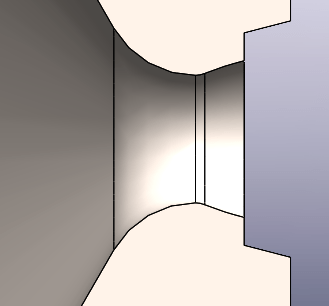
Fuel Injector
I designed an unlike doublet injector because it is simple and effectively mixes the fuel and oxidizer. This injector system was constrained by the minimum diameter commercially available DMLS (Direct Metal Laser Sintering) 3D printers can manufacture and by the need to have as small of a radius as possible to reduce droplet size. DMLS 3D printers cannot always print holes smaller than 0.5 mm.[12] The Pliny uses more liquid oxygen compared to gasoline. As a result, the gasoline side of the injector is constrained and the gasoline hole cannot have a diameter smaller than 0.5 mm. Since smaller holes result in higher injection velocities and smaller droplets, I decided to give the gasoline portion of the unlike doublet injector has a diameter of 0.6 mm, close to the minimum allowable size.
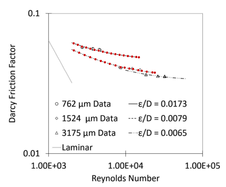
From this, I calculated the diameter of the oxygen hole. I used the Darcy-Weisbach equation to find a pressure loss which will produce my calculated mass flow rate. This calculated pressure loss was 244679 pascals. I then used this pressure loss and the mass flow rate of oxygen to find the diameter of the diameter of the oxygen hole. This diameter was 0.715 mm. To make the Darcy-Weisbach equation suitable for my calculations, I substituted terms until the only remaining variables were the mass flow rate, the diameter of the tube and the pressure loss. Every other term was a predefined constant. The Darcy Friction Factor was approximated using data from Understanding Flow Characteristics in Metal Additive Manufacturing.[13] One of the trend lines was for a tube with a diameter of 0.762 mm, which is close to the size of tube I desired. Since there was no equation for tubes with smaller diameters to make a weighted average with, I only used the 0.762 mm equation. Through substitution, I converted the Reynolds Number into a series of constants alongside the mass flow rate and the diameter of the tube. As a result, I had the Darcy Friction Factor and the rest of the Darcy-Weisbach equation in the previously stated terms.

μ is the dynamic viscosity and ρ is the density.
The fuel lines of the Pliny rocket engine extend linearly out 8 centimeters from the injector. The outer and inner diameters are both constant, with the outer diameter of 6.35 millimeters (1/4 of an inch) suitable for NPT threading to attach hoses to the engine.
Nozzle
I decided to design a parabolic nozzle using the procedure described in chapter 4 of Design of Liquid Rocket Engines by Huzel and Huang. Because my engine has a low chamber pressure, the area ratio of the throat and the atmosphere is extremely low, only 1.5. The graph provided by Huzel and Huang only extends down to an area ratio of 5.[14] This meant that I could not use the recommended initial and final angle at the same time. As a result, I used an exponential decay trend line to approximate the correct initial angle. At that point, I extended the parabola until the desired area ratio was achieved.
Igniter
I decided to design an electric ignition system. They are commonly used in rocket engines and can deliver large amounts of energy in a short period of time. Because commercially available sparkplugs are too large for my engine, I needed to create a custom ignition system. I use a large ceramic piece which has a small penetration that goes into the engine. This penetration starts out 10mm wide but is forced to narrow down to a slot to accommodate the fuel lines. The penetration has two holes . each occupied by 1 mm diameter wires. Since the typical process of pushing a wire through the holes will not produce a high quality seal, I plan to insert a wire with a substantially smaller diameter through each hole and then electroplate both wires until they reach the required outer diameter.

I intend to use Boron Nitride as the ceramic of choice unless it is cost prohibitive to do so because it has a dielectric strength of 40 kV/mm, much higher than air’s breakdown voltage of 3 kV/mm[18] and the highest of reasonably common ceramics.[15] This means that I can use a higher voltage in the igniter, reducing losses due to resistance and increasing the amount of power I can deliver via an electric arc. A larger power output means that more of the gasoline and oxygen can be heated to the ignition temperature before the fluids break the electric arc, increasing my chance of achieving successful ignition.
I made protrusions off of the combustion chamber with the diameter of 3M bolts for mounting the igniter onto the combustion chamber. Each of these protrusions will be threaded after the chamber is 3D printed with 3×0.5mm threads and have appropriately sized nuts placed on them to hold the igniter in place. I decided to do this to demonstrate that this is a possible way of attaching parts where bolts are difficult to place.
Window
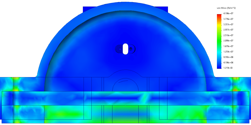
The window is a monolithic piece of sapphire. Sapphire has an excellent tensile strength and high melting point, allowing it to withstand the rigors of combustion without shattering. The mounting holes are larger than the bolts running through them since ceramic materials cannot be threaded. As a result, the window is sandwiched between the combustion chamber and a piece which distributes the load. To determine if the window is likely to fail, I preformed a finite element analysis. I set the inside of the rocket engine to experience the design pressure of 5 bar, used a series of bolts to mount the window in its proper location and assigned fixtures where the combustion chamber will be mounted to the test stand. Finite element analysis reveals that the window experiences no more than 20.9 MPa of stress, much less than sapphire’s tensile strength of 275 MPa.[16] As a result, Pliny’s 5mm thick window is unlikely to fail catastrophically during an engine test.
I also calculated the amount of heat delivered to the window during a 30 second test assuming a heat flux of 10 MW/m2. This heat was 129 Kilojoules. Assuming that the heat was used exclusively on heating material to the melting point and using 880 J/(kg*K) [17] as my specific heat, I found via the Q=mcΔT equation that the test would only push a layer 0.4395 mm thick to the melting point. As a result, the window is unlikely to fail during the first few test fires unless it suffers from thermal shock.
To film the engine, I will be using a slow motion camera to capture ignition and general fluid behavior during the test. This camera will most likely be a Freefly Wave camera since it can film at up to 9259 frames per second and the price of a rental is approximately $1000.
Next Steps
I am now focusing on the design of the test stand. This includes the propellant tanks, the valves attached to the engine, the method of measuring thrust and so on. Additionally, I will reach out to manufacturers of the various parts to determine the overall cost of the engine as designed. I plan to make posts about the design of the test stand, the assembly of the test stand and the results of the engine test as I continue to make progress on this project.
I’m looking forward to feedback about this project and what you all have to say about my design. Furthermore, if you would like to sponsor me or have me join your team, I would be deeply grateful. For all of your inquires (feedback, sponsorship, career opportunities), please send an email to gabrielsackinger@gmail.com.
Edits
11/29/2025: In the first published version of this post I stated that the breakdown voltage of air was 0.3 kV/mm. When I revisited this subject to design the electrical system, I found this value to be incorrect. The most commonly cited value is approximately 30 kV/cm, which is equivalent to 3 kV/mm.
Works Cited
[1] https://www.penflex.com/news/cryogenic-temperatures-austenitic-steels/
[2] https://cearun.grc.nasa.gov/cgi-bin/CEARUN/oxidizerSelect-Rev8.cgi
[3] (PDF) Octane Number Determination of Gasoline with a Phononic Crystal Sensor
[4] https://www.penflex.com/news/cryogenic-temperatures-austenitic-steels/
[5] https://onlinelibrary.wiley.com/doi/10.1155/2022/2171471
[6] https://www.jstage.jst.go.jp/article/tjsass/52/177/52_177_180/_pdf
[7] https://asm.matweb.com/search/SpecificMaterial.asp?bassnum=mq316q
[8] https://www.thyssenkrupp-materials.co.uk/stainless-steel-316l-14404.html
[10] https://arxiv.org/abs/2411.19792
[11] https://www.sfu.ca/~mbahrami/ENSC%20388/Notes/Staedy%20Conduction%20Heat%20Transfer.pdf
[12] https://forgelabs.com/design-guides/dmls
[13] https://www.osti.gov/servlets/purl/1982348
[14] https://ntrs.nasa.gov/citations/19710019929
[15] https://great-ceramic.com/advanced-ceramics-materials/properties/dielectric-strength/
[16] https://www.roditi.com/SingleCrystal/Sapphire/Properties.html