Over the two years I served as the Statics lead of the Human Powered Vehicle Project, I became a markedly better leader and engineer. I designed two frames of human powered vehicles and guided the second one through manufacturing. To make this happen, I designed, built and used a welding jig to weld the frame together. As I was a team lead, I delegated important tasks to my team members so they could gain experiences and grow into accomplished student engineers. Once the vehicle was completed, it competed in the e-HPVC competition funded by the overarching American Society of Mechanical Engineers, where it secured a podium position in the endurance race and secured the highest safety score of any vehicle.
I take some measure of pride in being a part of the Human Powered Vehicle Competition from the very beginning. The local student chapter of the American Society of Mechanical Engineers decided to start the Human Powered Vehicle project in order to give student engineers a chance to gain experience before moving on to another project. I joined the project because I had already applied to board positions in the student chapter and wanted to gain engineering experience. This project is divided into three subteams with their own leads, statics, dynamics and electrical. The statics subteam is responsible for the design of the frame, the seat of the vehicle, many of the electrical mounts and some of the ergonomics. I was tapped for the role of statics lead as the project commenced.
The first year of my tenure would be marked by innumerable challenges, some inevitable, others stemming from unique circumstances associated with the project’s beginning. Because the local American Society of Mechanical Engineers chapter started the project to give people experience, there were initially no recruiting standards for becoming part of the project. Anyone who wished to join could. Another issue was because of how engineering projects are handled at my university, there needs to be a team of higher ranking mechanical engineers with senior standing. As I am an aerospace engineer with junior standing, I could not be a part of this team. This necessitated the hiring of a second statics lead who I acted as a co-lead with. The third and greatest challenge, though, was the inevitable challenge all new projects face. Starting from absolutely nothing, our project had zero institutional knowledge and very little prior experience spread across the team. With all that being said, lets look at how my first year as statics lead played out.
Due to the aforementioned bureaucratic issues, the project only seriously began about halfway through the first quarter. My first goal was to determine the optimal design of the vehicle. This necessitates figuring out how many wheels it should have, how the rider should be seated, what material it should be made from and how the rollover protection system should be designed. A tricycle was chosen because it would provide greater stability when accounting for the rollover protection system. Furthermore, the seat was tilted backwards and made recumbent so the rider could be closer to the ground.
Over the course of the next few months, I worked with my team to design a frame and other parts of the vehicle until it was ready for fabrication. This frame was to be made from 6061 T6 aluminum tubing welded together because aluminum has a good strength to weight ratio. The primary design constraint I designed the frame around was the need for a rollover protection system that protects the rider from any impact. Essentially, a roll cage. The roll cage needed to survive a side load of 1330 Newtons and a top load of 2670 Newtons 12 degrees off vertical. These forces needed to travel through the frame to harness attachment points, indicating that the harness holding the rider in place can survive a roll. The frame was designed quickly to withstand both the side and top loads with a safety factor above 2.

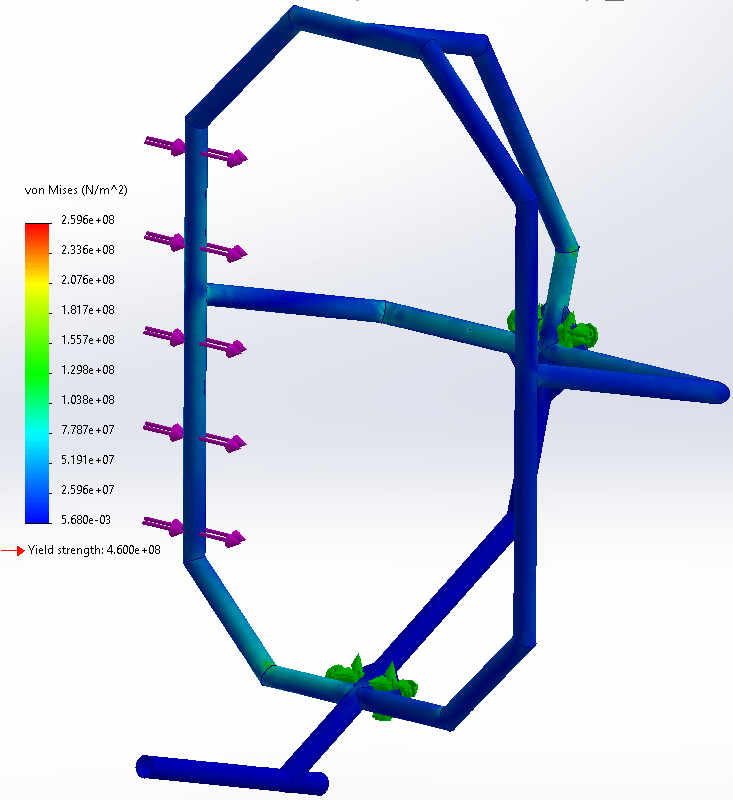
Figure 1: The results of the simulated horizontal force test on the first year’s frame, with a maximum stress of 1.24*108 N/m2
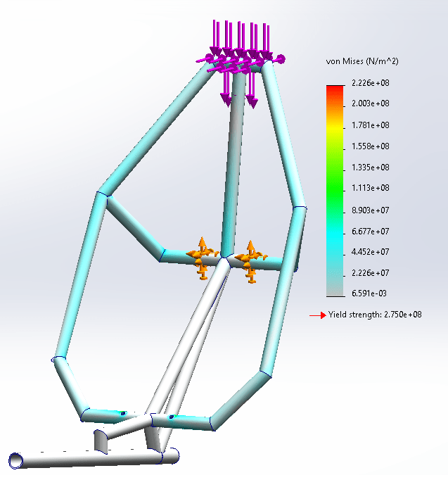
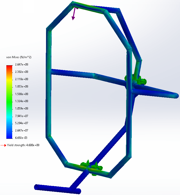
Figure 2: The results of the simulated vertical force test on the first year’s frame. Due to a simulation error, the maximum real stress was found to be 1.34*108 N/m2
In the caption of the simulated vertical force test, I noted that there was a simulation error in the static simulation. The maximum stress displayed by the legend is 2.23*108 N/m2, much larger than the 1.34*108 N/m2. However, the the error can be found by examining the simulation’s symmetry. The applied nearly vertical force has no horizontal component and the frame was designed to be symmetrical. Therefore, the stress distribution should be symmetrical. The peak stress was measured at the right side triple junction of the rollover protection bar and its support. Since nothing close to the peak stress was measured on the equivalent part of the left side, I concluded that the peak stress was fictional.
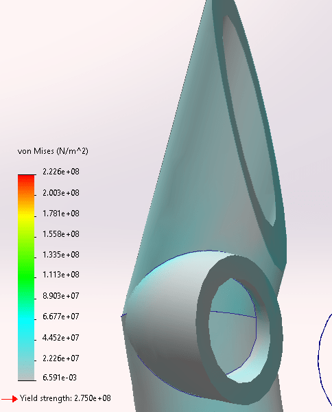
Figure 3: The left triple junction, where the stress in a simulation with symmetrical forces does not approach the peak stress.
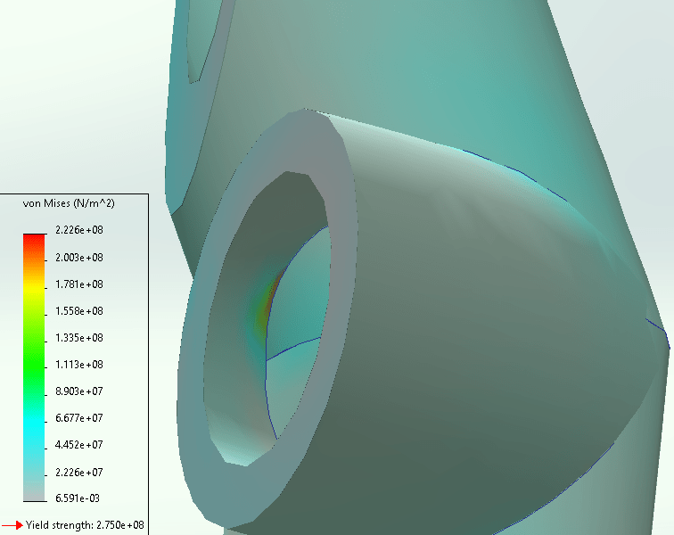
Figure 4: The right triple junction, which displays the fictional peak stress in the vertical force simulation.
Once the frame was fully designed, it was time for the frame to be manufactured. Unfortunately, aluminum is difficult to weld. Furthermore, I had hamstrung the design by making several features which are difficult to manufacture. This included joints where three or more tubes merge at a singular point and locations where two tubes gradually merged into each other. Since the University of California Irvine cannot manufacture aluminum, the project was forced to outsource to an external manufacturer. This was a poor decision on our part for two reasons. One, the manufacturer continuously gave overly optimistic estimates on when the frame would be completed, repeatedly stating over a three month period that the frame would be completed within a week. And two, our project’s lack of experience critically extended into manufacturing. I did not realize we provided insufficient information to the manufacturer until it was too late. Eventually, relations with the manufacturer degraded to a critical point. A week before the competition, the team visited the manufacturer and learned that the frame was not complete. As a result of this catastrophic manufacturing failure, my team could not compete the vehicle.
After this failure, I preformed an informal root cause analysis to determine what went wrong and how to ensure that next year’s project would succeed. First, our project’s lack of experience caused us to choose a material we could not effectively work. Second, large team sizes and a disorganized structure led to a breakdown in communication. I struggled to effectively manage my team of student engineers and communicate with the rest of management. Finally, I realized that I did not take enough personal responsibility during the project. While I doubts, I assumed that the rest of the team would ensure the frame’s completion. I should have acted on my fears, stepped up and acted before it was too late.

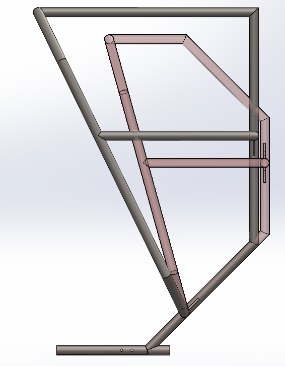
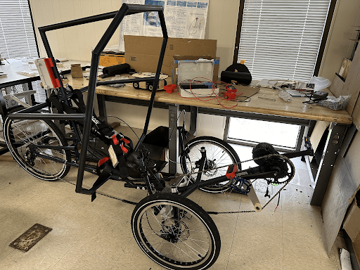
Figure 5: The frame submitted for manufacturing. Note several flaws in the frame’s design, such as two aluminum tubes slowly merging into each other.
To begin my second year as a statics lead for the Human Powered Vehicle Project, I implemented several changes to improve my team and ensure the success of the program. The project adopted a conventional recruitment model with applications, interviews and the best students being accepted. I took time to do some of the necessary interviews, determining which students would be good fits for the statics subteam. Ultimately, five student engineers joined the team. They were split between full time members and volunteers, with members needing to create progress slides reviewed by our advisor for a grade. As a result, I made sure that the volunteers would work on tasks which were not essential for the projects success. If they preformed well enough in the fall quarter, they would be promoted to full time members in the winter quarter. To ensure adequate communication within the statics subteam, I took the time to improve my documentation. By taking the simple step of taking publicly accessible notes during the meeting where I listed the tasks my team members needed to complete, I ensured that my team members always knew what they needed to do for the project.
During the first few weeks of the second year, my team’s focus was split between several objectives. Sunny Lin developed a geometry prototype, Thien Ngo focused on designing a battery box, Ethan Macias began work on a seat mount, Ocean Mou worked on splitting the frame for easier transport, and Henry Nguyen designed a harness mount. Of these tasks, the seat mount ultimately proved to be the most difficult and extensive, with its final design being fairly impressive. However, that is not my story to tell. At this time, I worked on the rear frame and investigated whether a fairing was viable. I did a clean sheet design of the second year’s frame and decided to use chromoly because the school has the equipment needed to weld it. This frame was simpler, with a spine arching over the rider and a roll cage affixed directly to the frame. The frame was split into two parts, attached via U-bolt. I ran the rear frame through a 1330 Newton horizontal load and a 2660 Newton vertical load. The frame passed these tests with a safety factor greater than 1.5.
As for a fairing, I quickly realized that the project did not have the time or money to invest in composites. Hence, I decided to investigate a design made from very thin metal sheets welded onto a metal truss. I made significant progress designing a fairing, testing several iterations in CFD simulations. These simulations tested the fairing in a 10 meter per second airflow, the speed the human powered vehicle aimed to attain. Ultimately, I reached a drag coefficient of 0.42 and a drag force of 16.6 Newtons. I intended to bring the drag coefficient down below 0.3, but circumstances forced me to abandon the fairing. The project did not have the time or money to build it.

At this point, the project was pushing to complete the geometry prototype. The geometry prototype is a design verification step I introduced where the statics team builds a wooden version of the frame in order to test its ergonomics and make sure the average rider could fit inside it. In order to do this, our team cut and glued wooden bars together. This process was time consuming as team members needed to hold parts of the prototype together for thirty minutes until the wood glue began to set. Clamps could not be used because the pieces lacked the flat surfaces needed. Meanwhile, we couldn’t use screws because we didn’t have a drill we could use. Regardless, the geometry prototype was completed to the point it could be used for a test. Several team members held the prototype and the seat in place, while an additional team member held the seat in place roughly where it was going to be mounted on the final design. After the test, it was clear that the frame needed to be modified, with the rollover protection bar tilted farther forwards and made slightly higher. I also removed a frame segment to simplify the geometry. At the end of the quarter the team pushed on to manufacture the main frame.
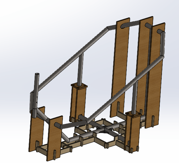
I spearheaded the team’s manufacturing push. I conceptualized a welding jig for the rear frame and made a CAD of the jig with a team member, Sunny Lin. Then, I laser cut the pieces of the welding jig and pushed on to weld the frame together. The welding jig was designed to hold metal tubing in place when I welded the frame together. To reduce the amount of material needed for the welding jig, I decided to weld some sections of the frame on a flat surface before placing them into the jig. Thus, the welding jig only needed to hold sections of the frame in place rather than every single tube. With this in mind, I designed the welding jig. This jig was made from 3/8ths inch thick plywood capable of holding the frame together in one piece. The jig held the frame ninety degrees from its final orientation, which made it easier to weld the frame together. Specifically, the supports of the roll cage were held vertically, making it easier to place the roll cage onto the frame. Overall, this welding jig was successful, allowing me to weld most of the rear frame together, though metal warping kept me from finishing the job.

However, I would make two design improvements for any future design. First, I would choose a thinner material because the thick wood made it incredibly difficult to manufacture with the schools laser cutter. I could have made the jig from thinner wood. Where I needed strength, I should have simply used multiple thin pieces glued to each other rather than one thick piece. Second, the welding jig did not provide adequate protections against metal warping. When welding, it is possible for metal to warp and fuse at an angle distinct from the intended angle. By welding segments of the frame flat before placing them onto the jig, I did not adequately protect myself from metal warping. I should have tasked my team members with creating secondary jigs to hold the flat sections in place while welding, thereby keeping metal warping in check.
Once the frame was fully welded together, my role in the project shifted. I spray-painted the frame with my subteam members near the end of winter quarter and requested a last minute harness replacement since the harness we had was missing a part required to function. Once these modifications were complete, the vehicle was ready to function. Over the subsequent couple of weeks before competition, I directed my statics subteam members to make small modifications to the vehicle. Ocean Mou designed, manufactured and mounted a side panel used to mount identifying information. Meanwhile, Sunny Lin created a headrest to make riding the vehicle easier. However, I reprioritized to testing, a design report and the future.
I preformed a rollover test where a person rested inside the vehicle while other people rolled over the vehicle. I flipped the vehicle over with the help of the electrical lead, Avi Singh and a statics subteam member, Henry Nugyen. Resting inside was Christian Mason, the project manager. If my frame was poorly designed, then either the harness holding him to the frame would fail or he would inadvertently touch the ground during the rollover. Both when the vehicle was on its side and its back, Christian was held far off the ground. Hence, the vehicle passed the rollover test and can adequately protect the rider from impacts.


For the competition, the team needed to complete a design report summarizing all the important information used to design the vehicle. I played a significant role writing this report, both by advocating for its completion and by completing significant sections of it. Early in the creation of the report, I tasked my subteam members to write down what they had worked on. Furthermore, I documented all the information needed to prove that the frame could survive the simulated loads along with a rollover test. Once this was complete, I worked with the rest of management to trim the design report down to the required length. To provide a concise source of information, the design report can only have 20 pages of content, anything more would not be considered by the judges of the ASME Human Powered Vehicle Competition. Hence, I was responsible for determining what information was necessary for the report and what could be sacrificed for concision. With little time to spare, the team completed the design report and submitted it to the Human Powered Vehicle Competition.
With the design report completed, it was time for the West Coast e-HPVC competition, hosted in Boise Idaho. It is hosted by the American Society of Mechanical Engineers, with teams from across the country racing against each other. The competition judges teams in three events, a design event, a speed event and an endurance event. Of these, the design event is given the most weight, with 50% of the scoring based off of it. It judges the teams design reports, with a high quality design report demonstrating their vehicles efficacy through a description, analysis and testing. Furthermore, large amounts of points are awarded to vehicles deemed safe due to the quality of the rollover protection system. Smaller amounts of points are awarded to teams who effectively present their reports and create aesthetically pleasing vehicles. The speed event is a drag race where human powered vehicles race against each other over a couple hundred meter course. The fastest vehicle is scored the highest, with the other vehicles scored based off of when they are eliminated. The final event is a 2.5 hour endurance race. The team which has the highest average speed wins, with the other team’s placement determined by their average speed. With all of this information known, my team descended onto Boise Idaho to compete. I was unable to attend, nevertheless, I awaited the results of the competition as they came into focus. The team’s performance in the drag event was middling, placing fifth among eight competing teams. While our placement in the design event was similar, our team scored first in the safety subcategory, demonstrating the strength of the rollover protection system. The team’s best result came in the endurance event, where we clinched a third place finish.
As my time as the statics lead of the human powered vehicle project came to a close, I took several measures to make sure that the project would continue to be successful. First, I made sure to teach one of my subteam members, Thien Ngo, how to build a welding jig. I made a practice part for him to design a welding jig around and then guided him through the process of designing a jig for that part. Second, I synthesized information my team learned from competition. Overall, it is not worth the effort designing a vehicle which can be split into multiple pieces. While a monolithic design would be harder to transport, the extra complexity of a frame split into multiple pieces was not worth the effort. Furthermore, the presence or absence of aerodynamic devices did not have a significant effect on the speed of the vehicles and may even be slightly harmful. Since human powered vehicles travel at low speeds, the reduction in drag is offset by an increase in weight. Finally, I took time to ensure that the project had a well defined structure for next years management to structure their project around. I handed off my role of statics lead to one of my subteam members, Ocean Mou.
In the span of two years, I pushed myself and others to excel and grow into the best possible engineers. The human powered vehicle project at UCI started with no experience or institutional knowledge and developed into a highly qualified team which secured a respectable finish in a national competition. I helped the project grow by synthesizing the lessons learned over two years and fostering a culture of responsibility. The team created a human powered vehicle we are all proud of and I will distantly watch the project continue to grow as it powers ever onwards!